
Process Role
A condenser removes heat as vapour becomes liquid. The supplied references include CDU overhead condensation, ammonia recovery in chemical production and alkylation refrigeration condensation. CO₂ process cooling can also produce condensate that must be separated. These examples establish different process roles, not a shared fluid specification or universal exchanger configuration.
Total and Partial Condensation
Define whether the selected duty requires total condensation, partial condensation or cooling with condensate removal. The CDU example explicitly describes full condensation. For another duty, identify the required vapour and liquid outlet conditions rather than assuming that all incoming vapour must become liquid.
For vapour mixtures, provide composition and relevant phase-property data. Identify non-condensable gases and the required outlet or venting arrangement. A thermal calculation needs the actual mixture and phase-change conditions; a single nominal vapour temperature is insufficient as a complete duty sheet.
Engineering Example: Ammonia Condensation Followed by Subcooling
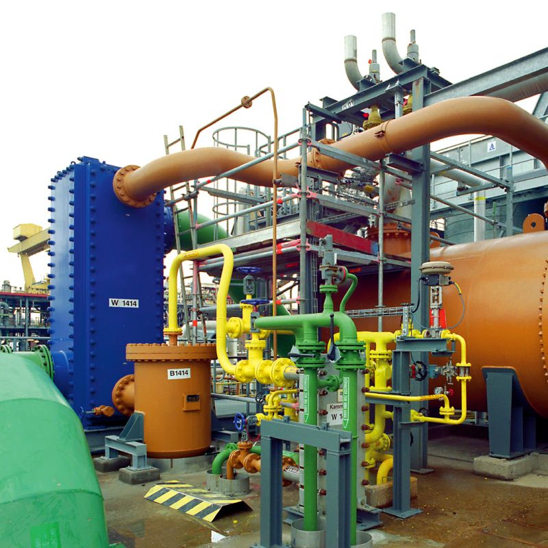
A published ammonia-recovery reference uses the first two passes for vapour condensation and the following two for liquid subcooling. Cooling water serves the exchanger. This illustrates a configuration in which the early passes remove phase-change heat and later passes cool the condensate further.
The source process logic places a shell-and-tube exchanger upstream, then a welded block unit for further condensation and subcooling. Collected liquid has tower-return and ammonia-recovery paths. No temperature, flow, operating pressure or heat-load values are provided.
This four-pass arrangement is one reference configuration, not a universal condenser design. Pass arrangement, liquid distribution and subcooling scope must be selected for the actual duty; no production or compressor-capacity gain is claimed here.
Key Engineering Inputs
Provide vapour composition, mass flow, inlet condition, condensation pressure, required outlet phase and temperature, and any specified condensate subcooling. Identify non-condensable content. Give cooling-medium inlet temperature, available flow, outlet limits and seasonal conditions.
State the allowed pressure drop for both circuits, with operating and design pressures clearly separated. Include material compatibility, contaminants, fouling history, connections, elevation and installation information relevant to drainage.
Design Challenges: Approach, Pressure Drop and Drainage
The available cooling-medium temperature and required outlet condition determine the thermal approach to assess. Review condensation and liquid subcooling as distinct parts of the heat balance. A multi-pass proposal needs a defined phase-change and liquid-cooling arrangement rather than an assumed standard sequence.
Check condensate removal, relevant venting and the pressure-loss allowance together. The reference ΔP in the CDU example is specific to that duty; it is not a general condenser value. For gas cooling with condensate removal, specify both cooling and downstream separation requirements.
Selection Considerations
Refinery overhead vapours, ammonia recovery and refrigeration condensation have different chemical and phase behaviours. Select the plate material and seals from the actual fluid and operating envelope.
What PANSTAR Needs for Selection
Send a condenser duty sheet describing total or partial condensation, fluid properties, normal and limiting flows, condensation pressure, outlet requirements, non-condensables, cooling-medium conditions and pressure-drop limits. Add drainage or venting interfaces, material requirements and the available layout. Identify whether subcooling is included in the exchanger scope.
Engineering background: Published multi-pass ammonia condensation/subcooling configuration; CDU full-condensation reference, p. 41; CO₂ cooling and condensate-removal context. The examples describe published third-party equipment, not PANSTAR installations.