
Crude Oil Preheating in Atmospheric Distillation Units
Compact Heat Recovery for Refinery Preheat Trains
Crude preheat trains recover heat from hot process streams before the crude enters the atmospheric furnace. Increasing useful heat recovery can reduce the heat that must be supplied by the furnace for the same throughput and target inlet condition.
At the hotter end of a preheat train, a close temperature approach can make additional recovery more demanding. A welded block heat exchanger can be considered where thermal performance, allowable pressure drop and the available installation space need to be balanced.
Why Consider a Welded Block Heat Exchanger?
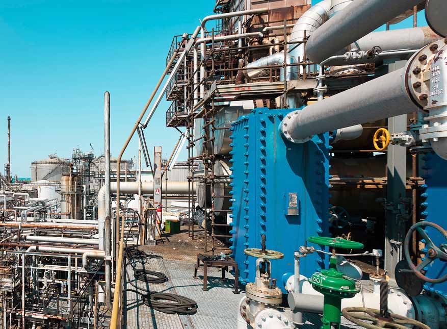
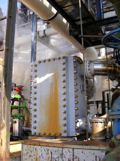
A compact plate arrangement provides heat-transfer surface within a relatively small installation envelope. For a refinery revamp, this can help integrate an additional recovery duty or assess an alternative to an existing exchanger arrangement.
The welded heat-transfer core has no inter-plate gaskets. Plate alloy, welds, panel seals and the approved design conditions still need to be selected for the actual hydrocarbon service.
Potential Benefits
Closer temperature approach can support additional process heat recovery. A higher crude outlet temperature can reduce downstream furnace duty, while a compact installation can help where plot space is limited. The achievable benefit depends on the paired streams, flow rates, fouling and hydraulic limits.
Selection for the Existing Preheat Train
Review both stream temperature profiles and flow ranges, crude properties, contaminants, fouling history and cleaning access. Check the pressure-drop allowance, piping connections, supports and maintenance clearances before defining the installation.
Assess the proposed exchanger as part of the complete preheat train, including startup and turndown. Atmospheric and vacuum distillation feed preheating, feed/effluent recovery and refinery debottlenecking each need a duty-specific thermal and hydraulic review.
Process Role
Refinery heat recovery connects a stream that must reject heat to another stream that can use it. The overhead-condensation references illustrate crude preheating and plant hot-water production. The design question is whether a useful heat sink is available at the required temperature and time, while the original cooling and process constraints remain satisfied.
Typical Heat-Integration Duties
Overhead heat instead of second-stage air cooling
The source describes replacing a second-stage overhead air-cooling duty with useful recovery to crude feed and plant hot water. This is a process-integration example, not proof that air cooling can be removed from any refinery. Review the complete operating range and the receiving system before defining the replacement scope.
Sour-water feed/effluent exchange
In the supplied SWS logic, hot stripped bottoms preheat incoming sour water. Bottoms then receive final cooling. Evaluate recovered heat and the downstream cooler separately; the process drawing supplies no numerical operating conditions.
Key Engineering Inputs
Match hot and cold stream flows, compositions, phase behaviour, inlet temperatures and required outlet limits. Define the required duty, available temperature levels and pressure-drop allowance for both circuits. Review the heat balance across normal, turndown and limiting cases.
For the receiving system, provide simultaneous operating hours and seasonal demand. For an existing installation, include fouling history, material compatibility, piping connections, space and cleaning access.
Engineering Example: Published CDU Overhead Duty
A published industrial reference describes complete condensation of CDU overhead vapour while preheating crude oil. The following values belong to that single reference duty. They are not a PANSTAR project, performance guarantee or general operating range.
| Parameter | Hot side | Cold side |
|---|---|---|
| Fluid | CDU overhead vapour; full condensation | Crude oil |
| Inlet → outlet temperature | 132.39 → 40°C | 14.33 → 54.66°C |
| Mass flow | 40,252 kg/h | 262,446 kg/h |
| Pressure drop, ΔP | 0.02 bar | 0.11 bar |
| Reported heat duty | 5.65 MW | |
| Reported plate material | C276 | |
Pressure-drop values are hydraulic requirements or reported reference values, not operating pressures. The source also lists design pressures and design temperatures; those limits have deliberately been kept out of this process table. No measured operating pressure is supplied.
The example demonstrates the information needed to evaluate coupled condensation and preheating. It does not establish that another fluid, plate pack or installed unit can reproduce the same duty or temperature profile.
Design Challenges and Selection Considerations
Assess the temperature approach, phase-change profile and hydraulic margin together. Overhead corrosion and crude-side fouling can influence materials, channel selection and maintenance planning. The example’s C276 plates identify that reference material only; use the actual chemistry and materials review for a new duty.
A recovery proposal also needs a defined installation envelope and stable heat demand. Assess the exchanger and surrounding process arrangement rather than translating a historical project’s energy or financial savings into a general equipment claim.
What PANSTAR Needs for Selection
Send a matched hot/cold stream datasheet, the heat-recovery objective, flow and temperature ranges, fluid properties, separate design and operating conditions, allowable pressure drops and operating schedules. Include the existing heat balance and any installation or maintenance restrictions. Define how recovered heat will be measured after commissioning.
Engineering background: Published CDU reference duty, p. 41; Overhead heat-recovery process description, pp. 26–29. The examples describe published third-party equipment, not PANSTAR installations.