TIG welding · Argon arc
Broader fusion profile in the illustrated sample.
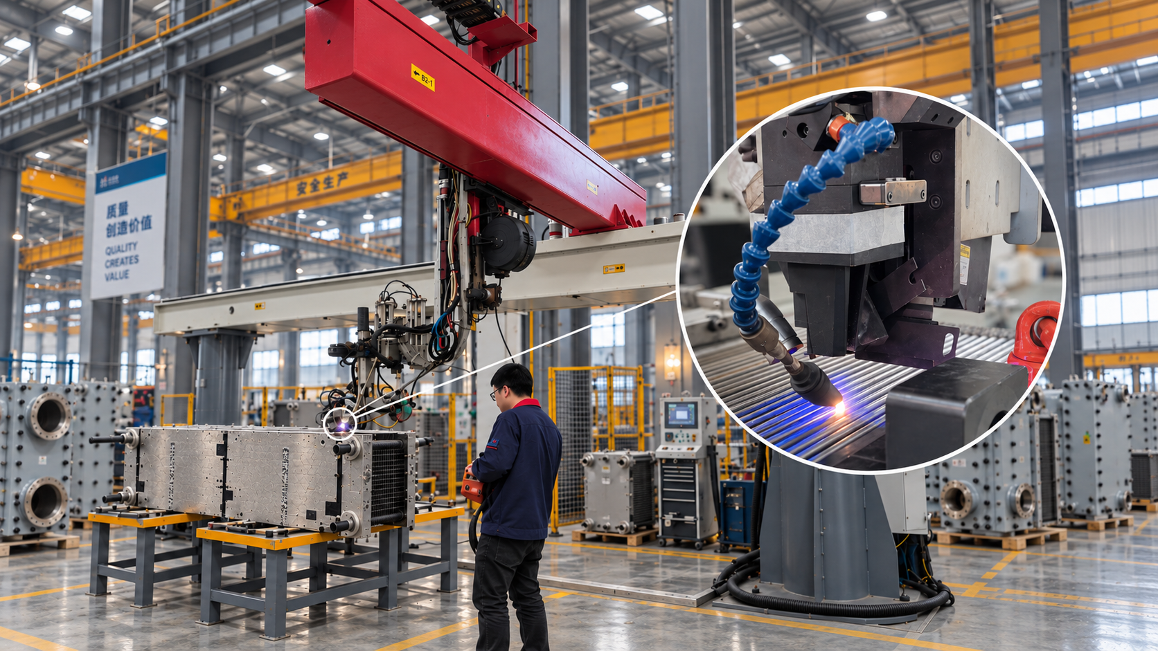
Automatic laser welding forms the HEXCBLOC welded plate pack. Controlled weld penetration creates the joints that keep hot and cold flow channels separate.
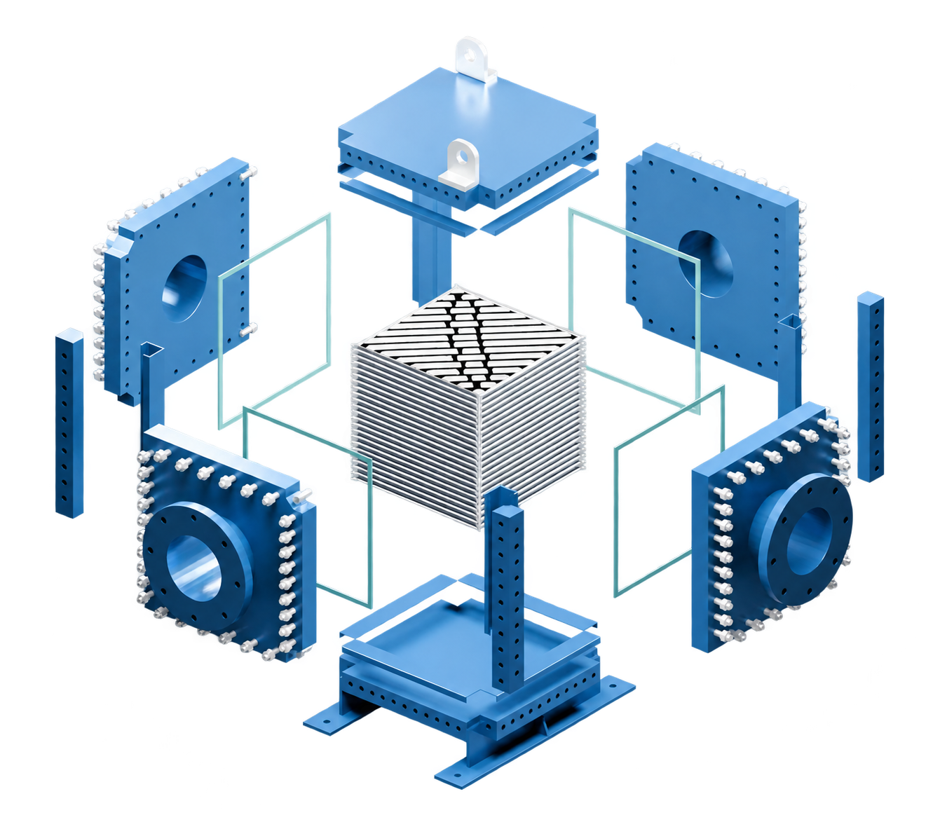
Rotate the assembly, open the casing or switch to Flow principle to follow the two separate circuits.
Broader fusion profile in the illustrated sample.
Concentrated fusion profile in the illustrated sample.
A focused laser can produce a deep, narrow weld with less heat spreading into the surrounding plate.
Localized heating helps limit distortion and thermal changes beside the weld.
Joint fit-up and welding parameters are selected to achieve the required fusion through the joint.
2 mm penetration in the shown sample
PANSTAR’s supplied material reports 2 mm weld penetration and specimen weld strength above the parent material. The photographs illustrate the sample and test setup; a numerical strength result is not provided.
Penetration alone does not establish strength. Production acceptance depends on material, joint geometry, welding procedure and inspection results.
Images and sample claims: PANSTAR supplied technical material. Laser welding principles · TWI
Alternate plate edges are welded to form separate hot and cold channels. The animation shows the weld sequence and open flow passages.
The exact joint geometry should be confirmed from the approved manufacturer drawing for the equipment being assessed.
The formed lips meet at a butt weld. Joint accessibility, surface continuity and cleanability depend on the approved plate profile, weld execution and service conditions.
Depending on geometry, fluid properties and operating conditions, a residual recess may influence cleanability and deposit behaviour. The actual section must be verified from the relevant production drawing.
Cleanability and deposit behaviour depend on the actual recess dimensions, fluid composition, temperature, alloy, weld quality, velocity and cleaning method. The schematics support an engineering discussion; they do not establish the construction or performance of a specific third-party unit.
The alternative end-welded schematic is illustrative. It is not a verified production section for a specific third-party product. Schematics are not to scale and do not show calculated flow fields.
Technical references: Alfa Laval · C-Weld · Alleima · Crevice corrosion
Compare exchanger designs, explore the model range and define your process duty.
Explore HEXCBLOC models and selection